
Tension Control System
Background
It was mentioned to me that the pilot scale coater was changing quality and thickness as the coating process went on. I began researching why this might be, and found that this coater had a fixed speed throughout the coating process. This is an issue, because as one roll gets thicker and another loses layers, the changing radius means that the tension changes in the coating process. I sought to create a tension control system for this
Initial Torque Analysis
Before I started the process I used torque wrenches and rulers to create a chart of the output torque as a function of the motors speed. The formula for tension in coating is Tension=Torque/Radius, so knowing the torque at a given speed and the rolls radius, tension could be calculated. This would later be utilized in my code.
Open Loop Solution
The first solution was open loop. Using the function I had generated, I used an ultrasonic sensor to measure the radius of the input roll. My function generated what the necessary speed of the motor must be to maintain a constant tension. This was displayed on an LCD for manual speed adjustment.
This solution did result in less of the oddities noticed earlier, though was far from perfect
Closed Loop Solution
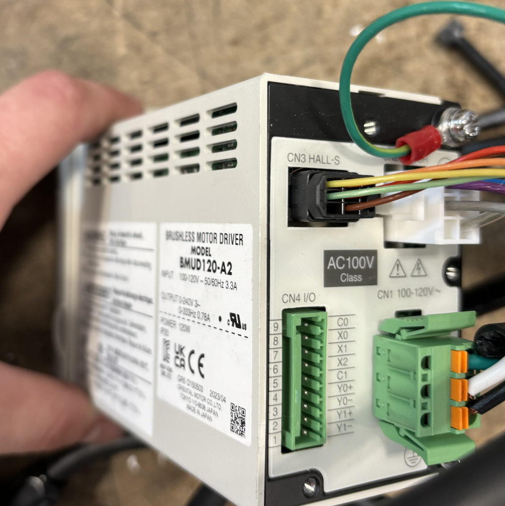
The next step was to create a closed loop. I ordered the necessary components, including a new motor controller (above) for the output roller. I ordered new spindle components with load cells that would output the read tension. Using a PLC the speed would be adjusted until the tension matched what was wanted, utilizing PID to approach and maintain this number. My internship ended before the load cell components arrived.