
Warm Turkey Shell and Casing Design
I did all CAD development for this project, with the largest component of that being our casings. We needed a system that was designed for manufacturing and assembly, and adapted as we improved our internal electronics
Customer Interviews
The first steps involved collecting client feedback, asking nicotine users what they were looking for in the shape and feel of a nicotine product. Over 100 interviews were conducted
Reverse Engineering
Current market products were taken apart to visualize how their casings were designed. A BOM for each individual vape was created to see how they compare in material selection and components
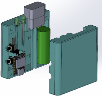
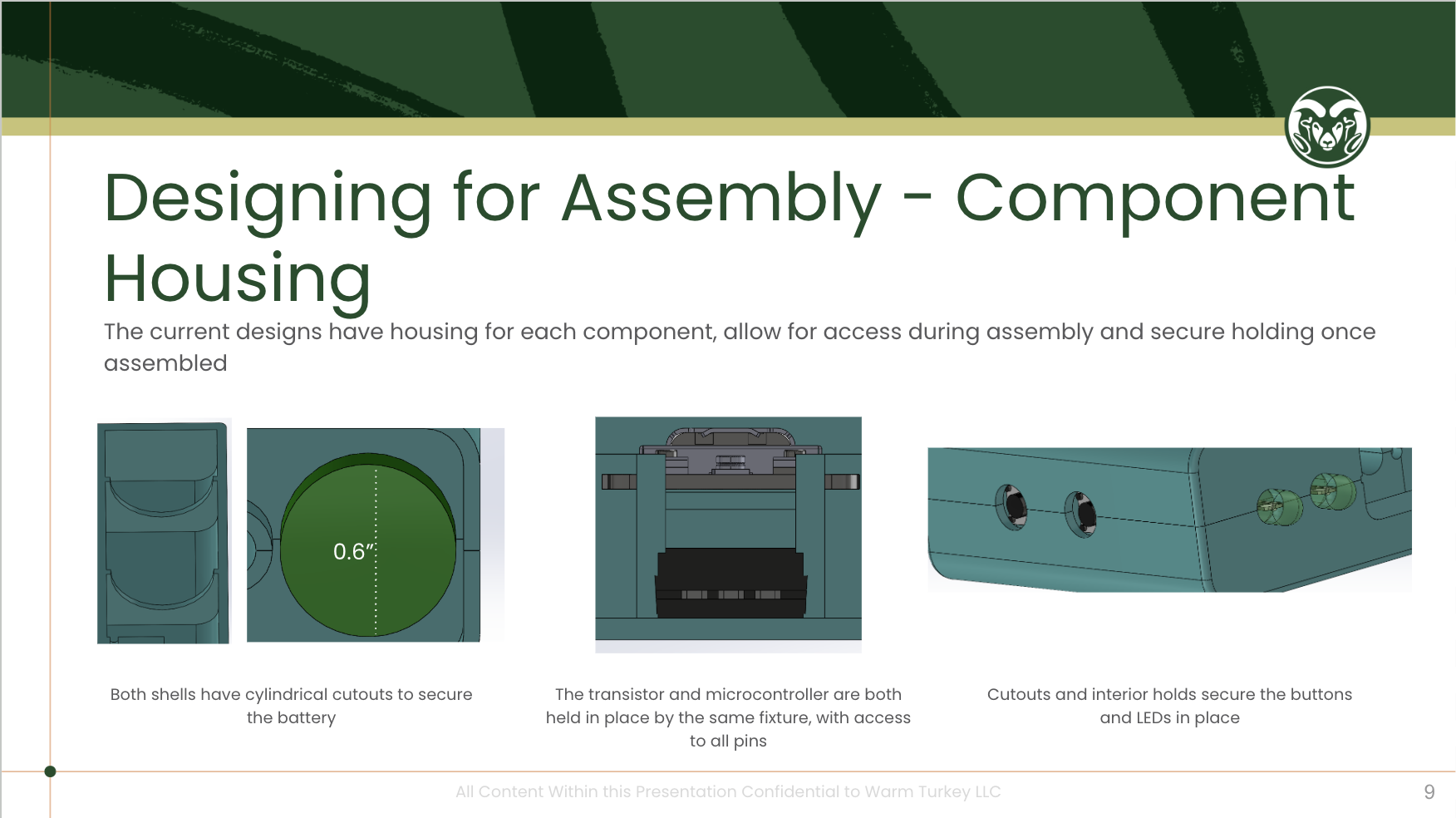
Iteration 1
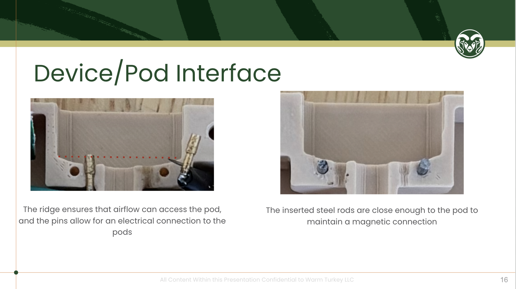
Before we developed our PCB, we designed the case around our free wired electronics. I manually machined brass and steel pins for electrical and magnetic contacts to our pod.
The casing was a 2 shell system, where one side of the shell held locations for our electrical components, and the other shell was screwed in place to secure them
The following are slides from our comprehensive design review discussing this design, you do not need to read them, they were added mainly for the images they provide
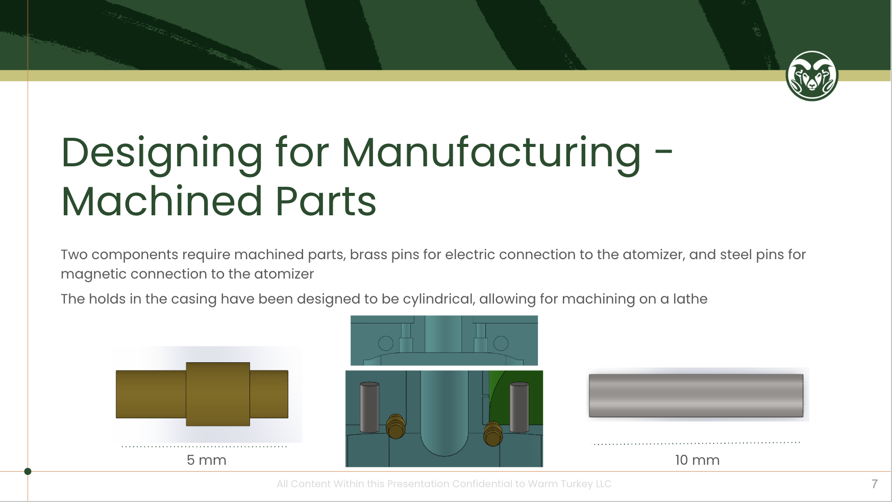
Iteration 1 Result
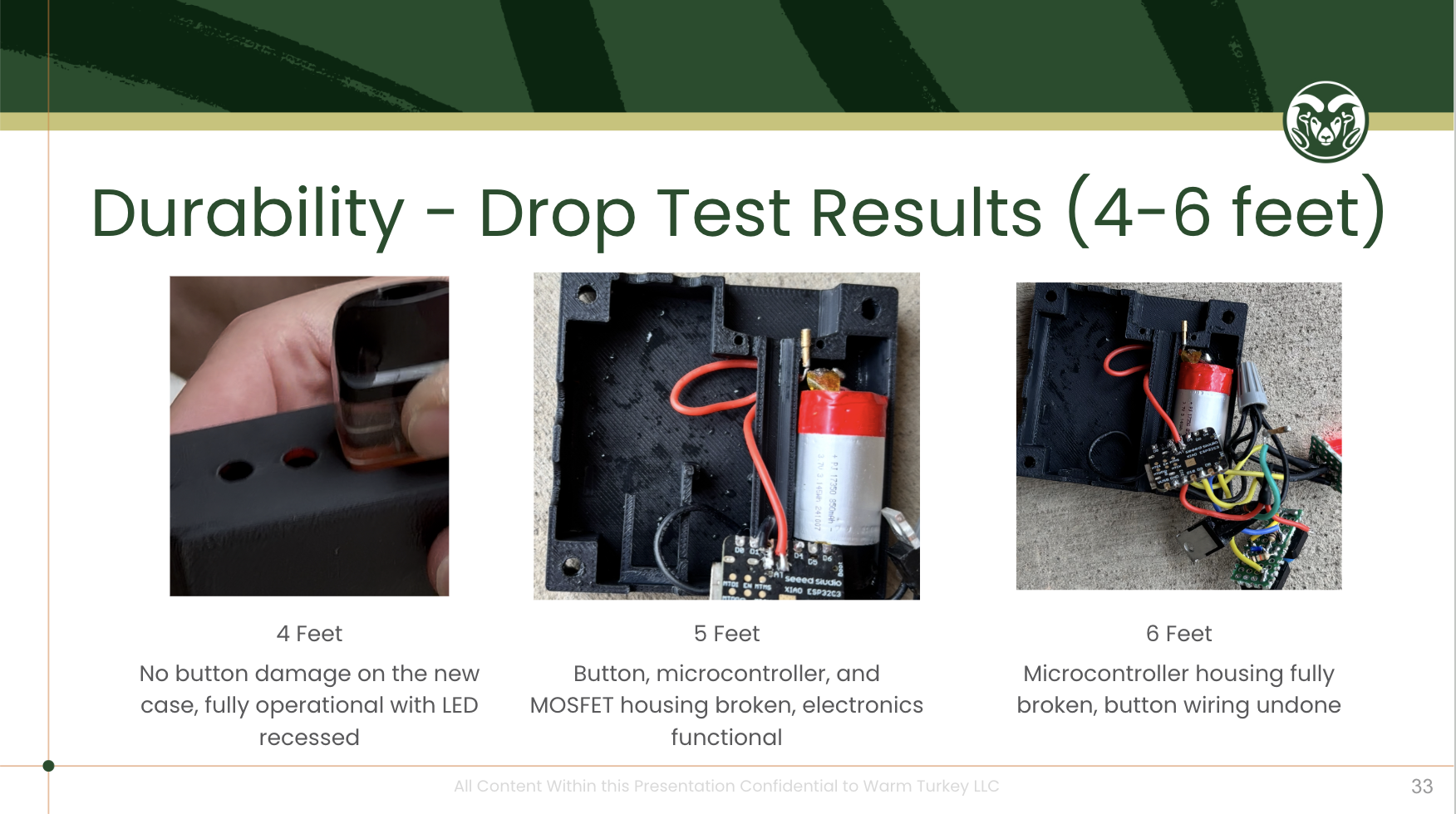
This design was incredibly susceptible to fall damage. The choice of PLA was a mistake, while it was free to students it is not a proper choice for anything that needs to stand up to damage. The brass pins also recessed into the shell upon impact, losing their electrical contact. Many of the components housings were not sufficiently sized to deal with impact
Iteration 2
Iteration 2 was designed purely for testing. It was assumed that a cylindrical shape would best fit in our testing apparatus.
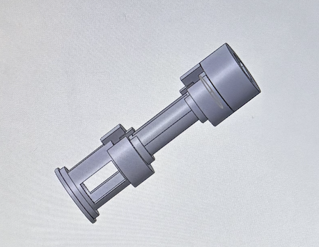
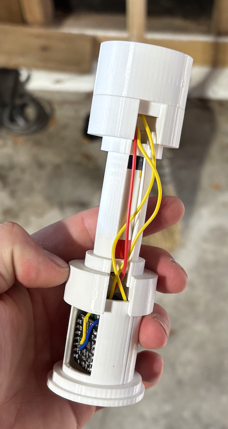
Modularity was the focus for this design, with each electric component having its own housing that was connected to the rest of the system. A large sleeve would cover all components, and internal slots were made for the wires to pass through
Iteration 2 Result
This design functionally worked, but before testing was scheduled our PCBs arrived so we scrapped it to focus on the more reliable electrical system
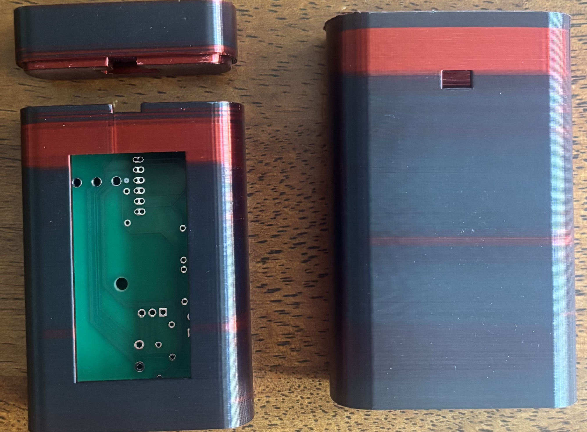
Iteration 3
Iteration 3 was designed around our PCBs. After more reverse engineering we found a system with an internal skeleton and external sleeve that we liked and wanted to emulate. ABS was chosen for the material selection, and 3D printing the choice of manufacturing
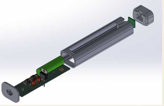
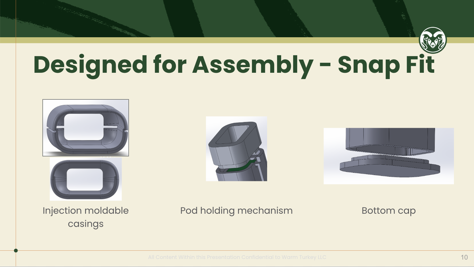
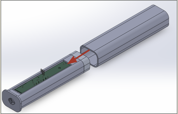
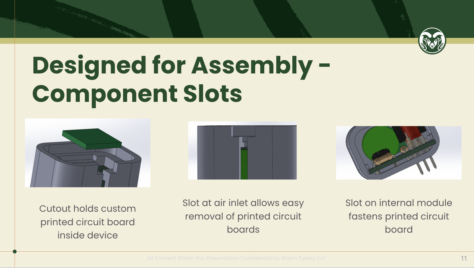
As the following slides show, each part of our skeleton and shell had tolerances chosen for an interference fit, and there were component slots for the PCBs
Iteration 3 Result
This design easily had our best design for assembly. It was a quick and easy process to assemble each prototype once the PCBs were assembled. The design also survived all drop tests that it was put through.
Iteration 4 (Final)
Iteration 4 was made to fit a smaller PCB and an injection molding friendly shell. It follows the same idea as iteration 3, just in a different form factor
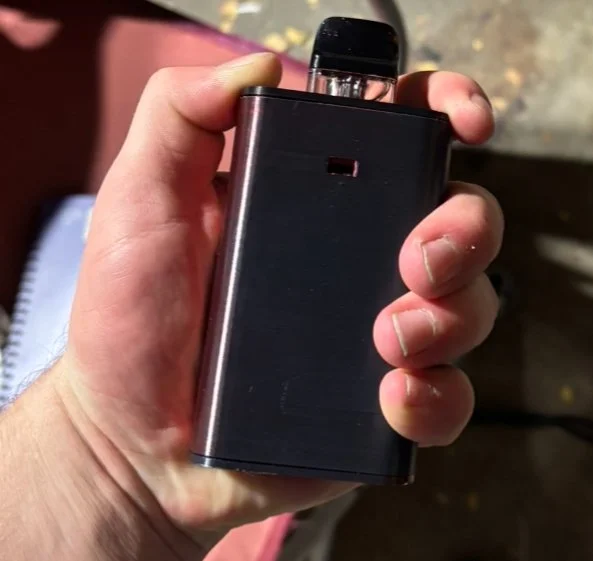
Iteration 4 Result
Iteration 4 fully worked and scored higher in interviews compared to iteration 3
Review
As we moved through this project, I was able to adjust the form factor to match our needs at the time. The design adjusted to match our manufacturing capabilities, as well as our electronics